ALL PRODUCTS
- Solar Panel
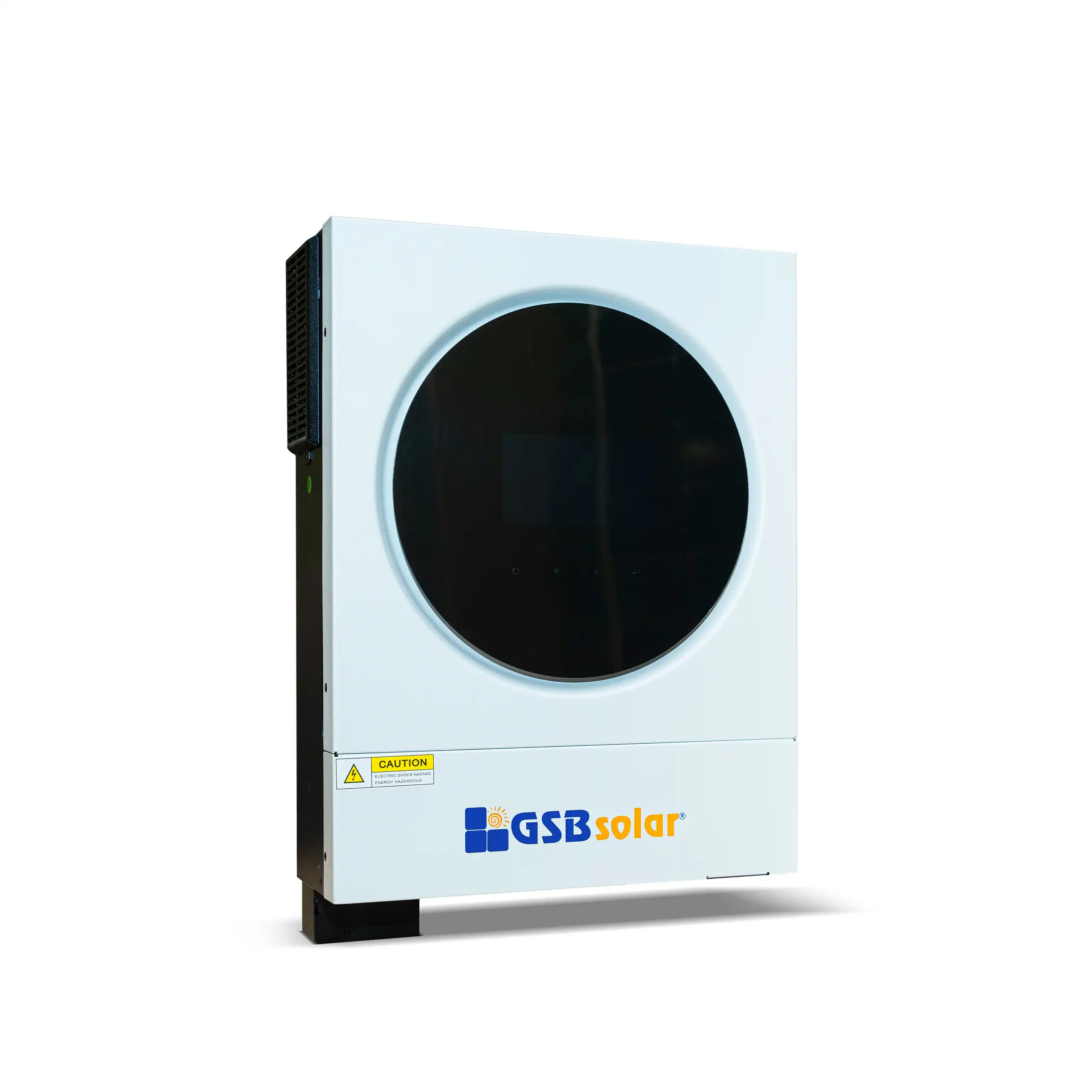
- Hybrid Inverter
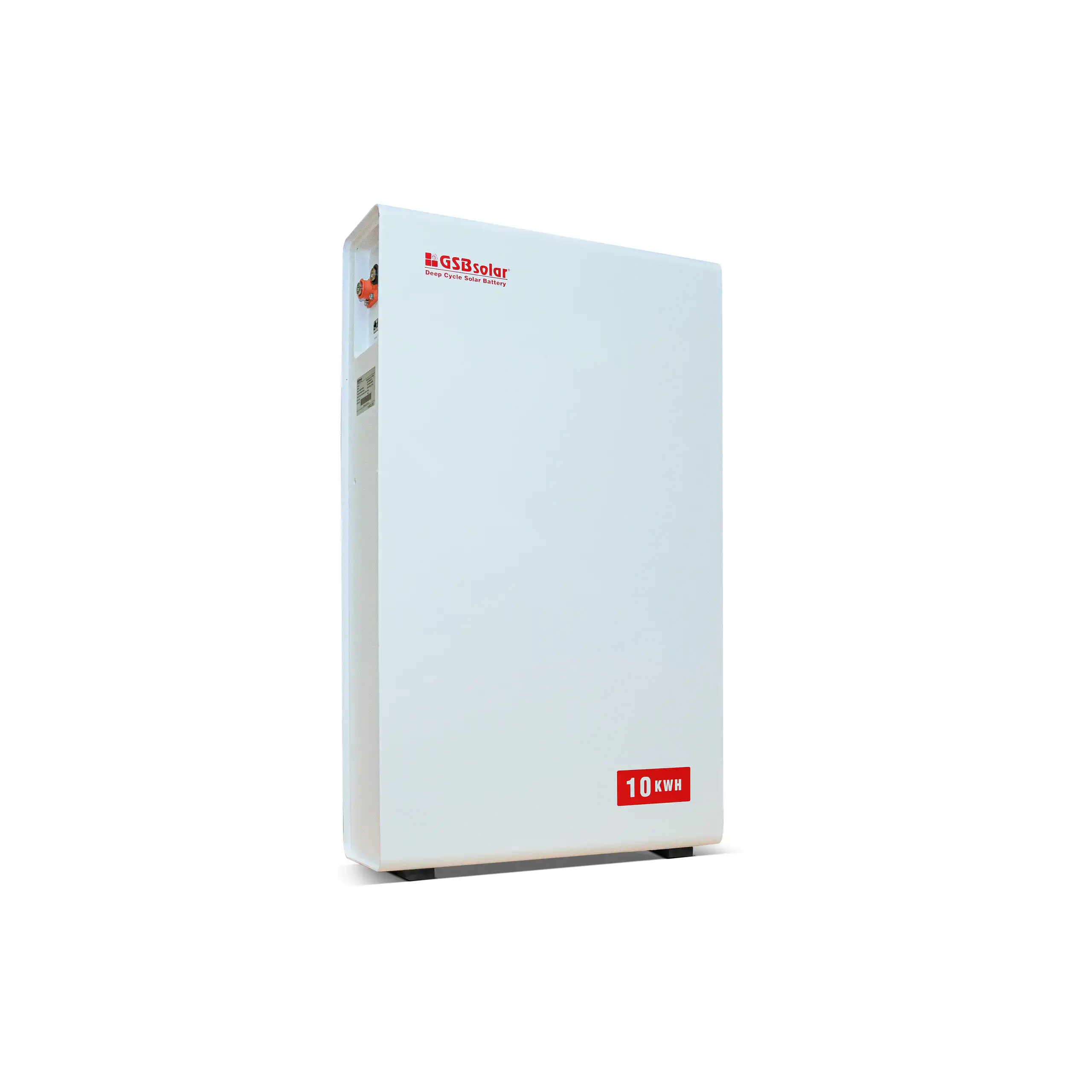
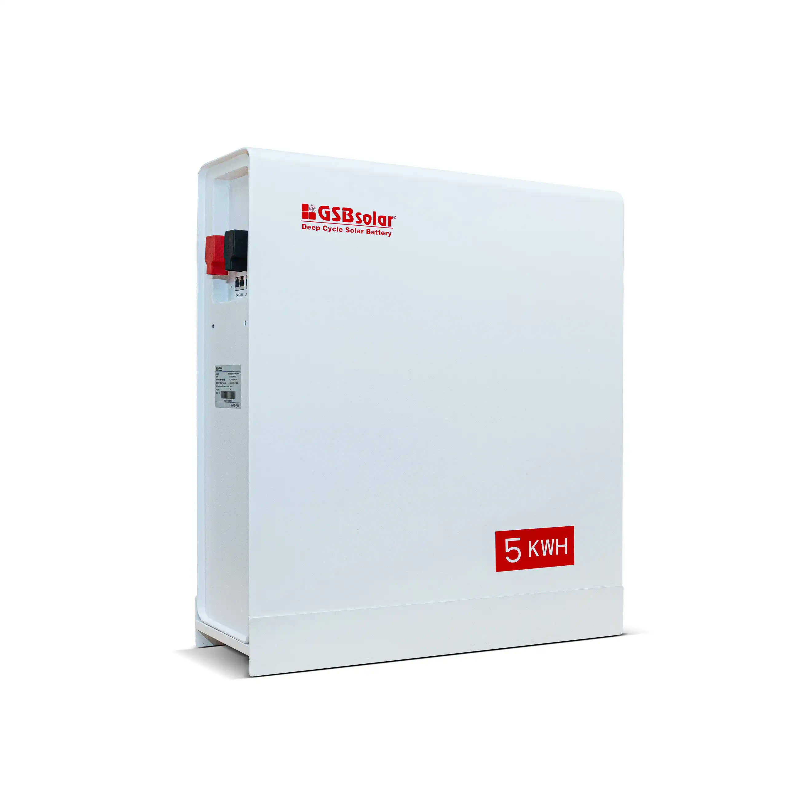
- Lithium Battery
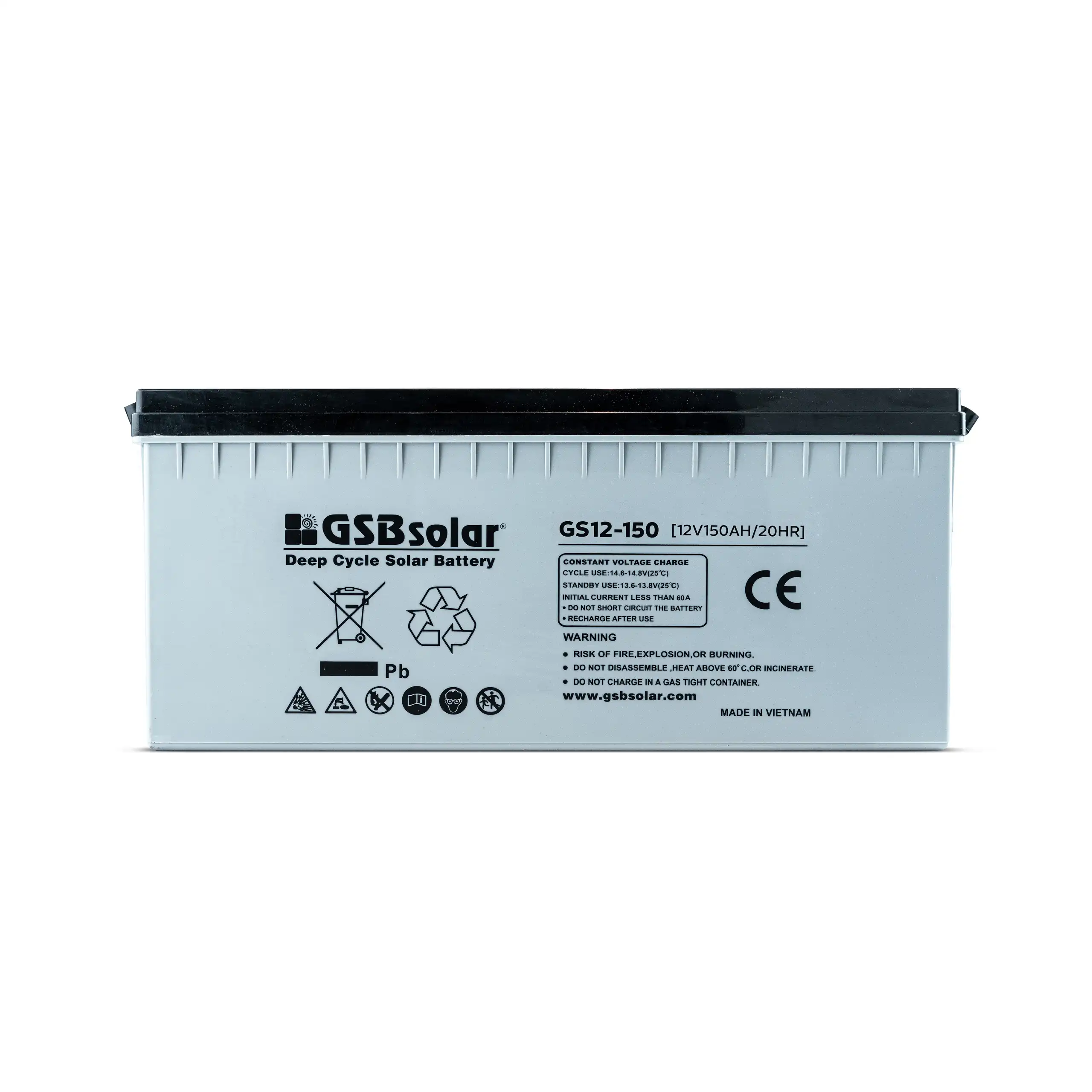
GSB SOLAR LITHIUM BATTERIES
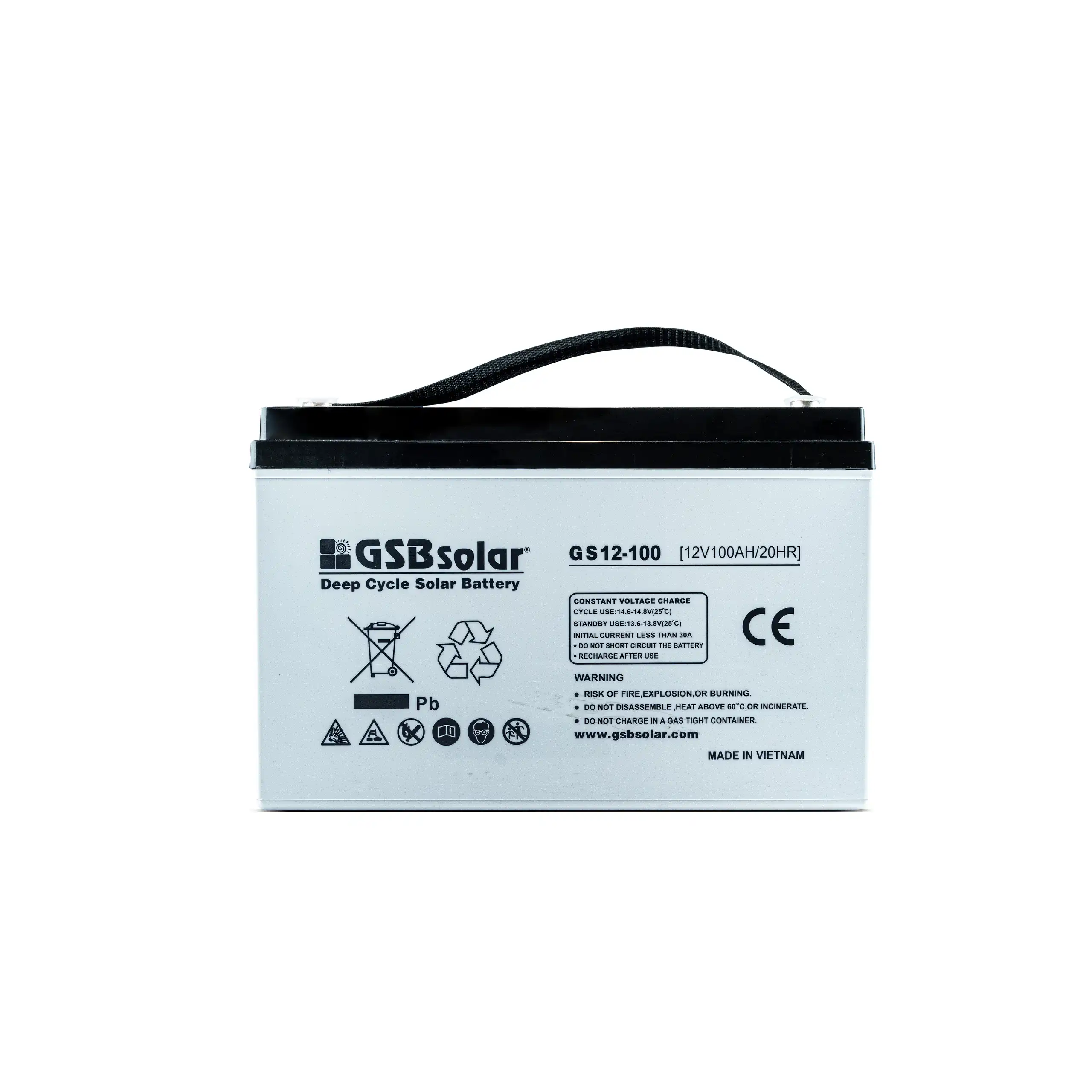
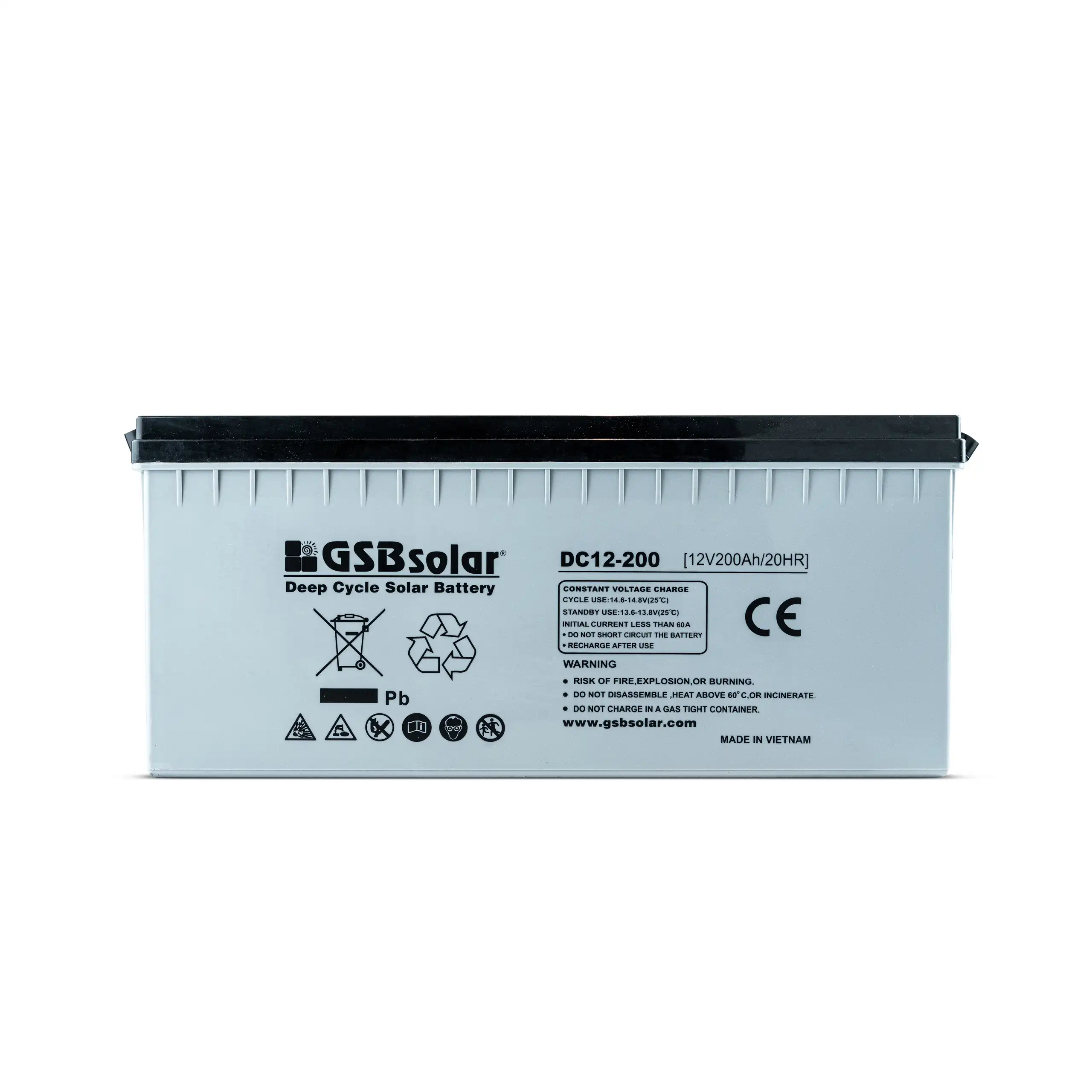
- Gel Battery
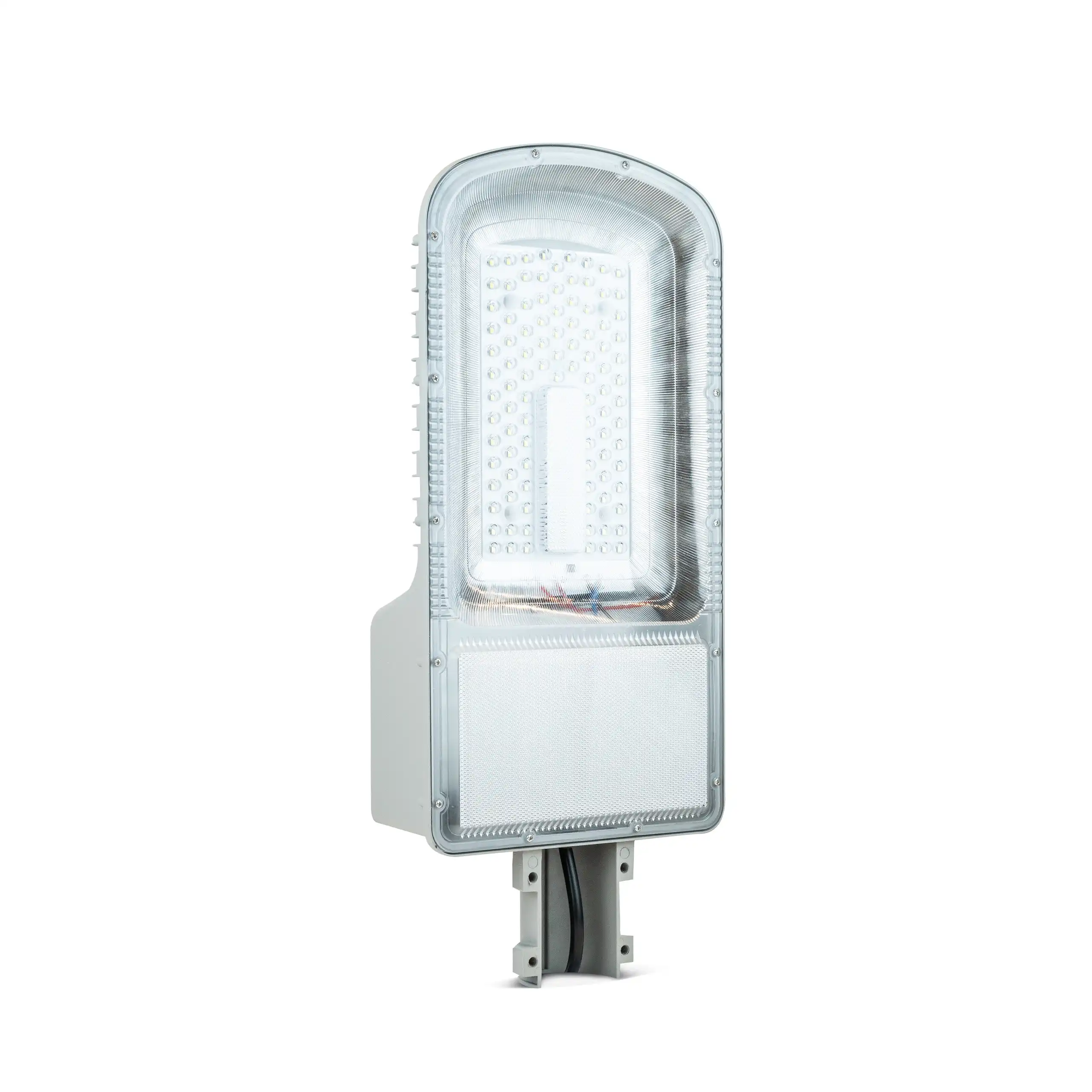
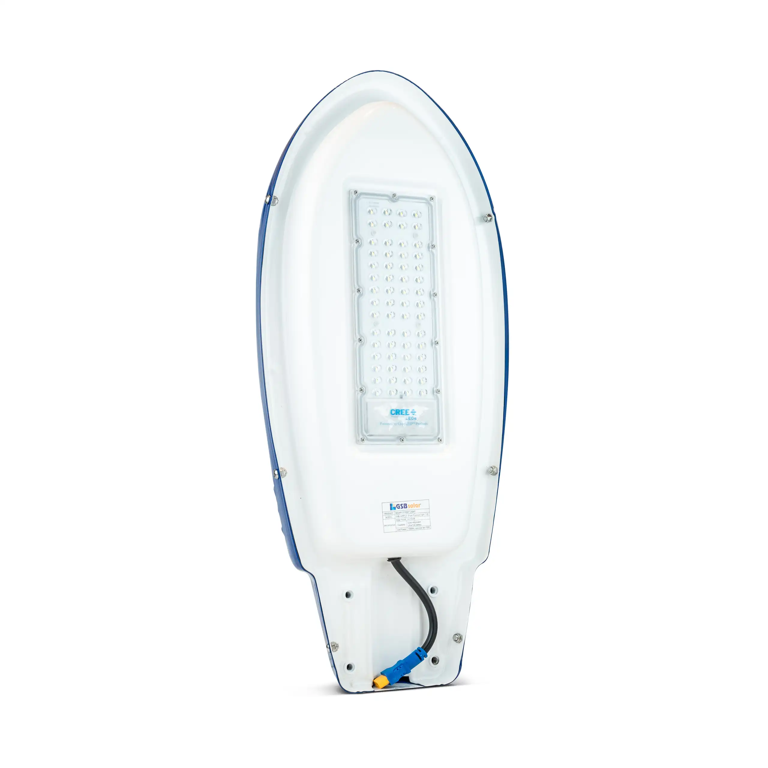
- Solar Street Lights
- Pump Inverter
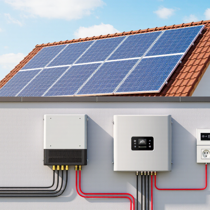
A solar panel inverter is the working link between rooftop sunlight and usable household electricity. Solar panels produce direct current (DC), but most homes and businesses use alternating current (AC). The inverter changes that electricity into a form that appliances, batteries, and the utility grid can accept. Without it, a bright afternoon would create power that ordinary wall outlets could not use.
Solar design expert Steven Strong has described the inverter as “the heart of a solar electric system.” The comparison is useful. An inverter monitors voltage, controls energy flow, and disconnects the system during certain grid faults. Many modern units also track panel performance, communicate with monitoring apps, and manage battery charging. Some models sit beneath individual panels, while larger string inverters serve several modules together.
The details matter. Shade, heat, wiring length, and panel orientation can affect inverter performance. A correctly sized unit may reduce energy losses and operate more reliably over time. However, no inverter removes every weakness in a solar array. It cannot create sunlight during a storm. It cannot fix poorly installed wiring. It also has electronic components that may age sooner than the panels.
That is where real-world experience becomes important. A professional assessment should review local conditions, equipment ratings, ventilation, maintenance access, and applicable electrical requirements. Product labels alone are not enough. This guide explains how a solar panel inverter works, what happens inside it, and how its design influences a complete solar energy system. The simple version is helpful, but incomplete.
A solar panel inverter is the system’s electrical translator. Solar modules produce direct current (DC), while homes and public grids generally use alternating current (AC). The inverter converts DC into usable AC with controlled voltage, frequency, and waveform. One job, repeated reliably.
Its core purpose is broader than conversion. The inverter tracks each array’s maximum power point, helping panels produce useful energy during changing sunlight. It also monitors temperature, voltage, insulation, and grid conditions. If the grid becomes unsafe, protective controls can disconnect the system. In practical commissioning, these functions matter as much as the advertised conversion efficiency.
The scale is significant. The IEA Photovoltaic Power Systems Programme reported that global solar capacity passed 1.6 terawatts by the end of 2023. Every additional installation increases the importance of stable power electronics. NREL research on inverter-based resources also highlights advanced functions, including voltage support and grid-forming operation. These features can help solar systems respond more actively to network needs, especially as conventional generators retire.
Still, the basic explanation can sound too neat. An inverter cannot create sunlight, remove poor wiring, or repair shaded modules. Its performance depends on design, installation, ventilation, and accurate settings. A high efficiency figure may also describe laboratory conditions, not every hot afternoon on a roof. That distinction deserves attention. Inverter selection should therefore consider local grid rules, expected loads, maintenance access, and future battery integration, not only the percentage printed on a specification sheet.
A solar panel inverter changes the panels’ direct current into usable alternating current for a home or business. It also monitors voltage, frequency, and system safety. The main inverter types differ by location, wiring, and power-handling structure.
A string inverter connects several panels in one series circuit. It usually sits on a wall near the electrical equipment. This design is simple, cost-effective, and easy to service. However, shade on one panel can reduce output across the string.
A microinverter attaches beneath each panel. Each unit performs the conversion separately, so panels can work more independently. The roof then carries more electronic devices, which may complicate replacement work.
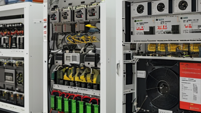
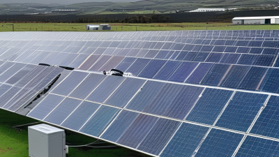
A central inverter uses one large conversion unit for many panels. It suits utility-scale arrays but requires careful cable planning and suitable ventilation. Large power, concentrated in one cabinet.
A hybrid inverter adds battery control to the solar conversion process. Its structure includes bidirectional power electronics, allowing energy to move between panels, batteries, the grid, and household loads.
During a site assessment, technicians should check roof shade, cable distance, operating voltage, and battery capacity before choosing a design. Heat matters too. An enclosed inverter may lose efficiency when airflow is poor.
No layout wins every time. I would not treat the cheapest structure as the most reliable choice, because service access and future expansion can change the real cost. Structural differences often matter more than appearance.
Solar panels produce direct current, but homes usually use alternating current. The inverter makes solar energy usable electrical power. It changes the panels’ steady DC output into AC electricity for lights, appliances, and other household circuits. This conversion happens continuously while sunlight is available. During system checks, I have seen small shade patterns reduce output more than owners expected. A clean panel does not always mean a perfectly productive system.
Inside the inverter, power electronics rapidly reshape the electrical signal. A control system tracks the panels’ changing voltage and current to collect useful energy. This process is called maximum power point tracking. The inverter also monitors frequency, voltage, temperature, and grid conditions. If the grid becomes unsafe, it can stop sending electricity outward. That protective response is essential. It also shows why professional installation and local electrical rules matter. Solar power is not simply “plug and play.” The explanation can sound tidy, yet real performance depends on weather, wiring, orientation, and equipment condition. Small losses add up.
Tips: Check the inverter’s display for unusual warnings, heat, or sudden production changes. Keep nearby vents clear and avoid covering the unit. Ask a qualified technician to inspect faults, especially after storms. Compare daily production under similar weather, not just one cloudy afternoon. My own judgment would remain cautious here: a low reading may indicate a fault, but it may also reflect seasonal sunlight or temporary shade.
How Solar Energy Becomes Usable Electrical Power
This representative clear-sky profile shows the direct-current (DC) electricity produced by a 5 kW solar array and the alternating-current (AC) electricity delivered after inverter conversion. The inverter output is slightly lower because typical conversion losses keep operating efficiency below 100%, generally around 96–98% under favorable conditions.
A solar panel inverter is the control center between photovoltaic modules and the electrical grid. Panels produce direct current, but most buildings use alternating current. The inverter converts it safely and continuously.
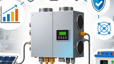
Inside, several components share the work. The maximum power point tracker, or MPPT, adjusts operating voltage as sunlight and temperature change. It helps each panel string produce useful power, even under uneven conditions. Semiconductor switches then reshape the current into a clean AC waveform. A transformer, where included, manages voltage isolation and electrical levels. Sensors monitor voltage, frequency, temperature, and insulation.
Protection circuits matter just as much. They can disconnect the system during grid faults, overheating, or abnormal voltage. A communication board records production and may flag a weak string. Small details matter here. Loose terminals can create heat. Poor ventilation can shorten component life.
The IEA PVPS Trends 2024 report recorded about 1,411 GW of global photovoltaic capacity by the end of 2023. That scale increases the importance of dependable inverter design and maintenance. Fraunhofer ISE’s Photovoltaics Report also shows module efficiencies continuing to rise, which can increase DC input and thermal stress. More power is not automatically better. In field inspections, dust, shading, and aging connections still undermine performance. An inverter may be technically sound, yet the whole system can disappoint. That is the part worth questioning.
A solar panel inverter changes direct current from the panels into usable alternating current for a home. It also monitors voltage, temperature, and grid conditions. When sunlight changes, the inverter adjusts its output to maintain stable electricity. In practical installations, this small device often determines how efficiently the whole system performs.
Inverter selection depends on panel capacity, roof design, shading, climate, and local electrical rules. A roof with several shaded areas may need module-level control. A simple, unshaded roof may work well with one central unit. Efficiency ratings matter, but real performance also depends on heat, dust, cable length, and poor installation. A higher rating does not guarantee better results. That assumption deserves careful review. Field inspections often reveal loose connections or blocked ventilation, not defective equipment. Battery storage also changes the decision, because charging and discharging require suitable power control. Check warranty terms, service support, monitoring quality, and expected operating temperatures before choosing.
Tips: Match inverter capacity with the panel array, but avoid extreme oversizing. Leave clear airflow around the equipment. Review monthly production data for unusual drops. Clean nearby surfaces when dust builds up. Ask a qualified electrician to verify wiring, grounding, and protective devices. Local conditions can change the ideal choice. A design that performs well in one location may disappoint elsewhere.
| Category | Data Dimension | Typical Information or Range | How It Works or Why It Matters | Selection and Performance Guidance |
|---|---|---|---|---|
| Basic Function | Primary role | Converts direct current (DC) from solar modules into alternating current (AC) | The solar panels produce DC electricity, while most household appliances and the utility grid use AC electricity. | Choose an inverter that matches the electrical requirements of the building, battery system, and local grid. |
| Basic Function | Grid synchronization | Matches grid voltage, frequency, and phase | A grid-connected inverter continuously monitors the utility supply and adjusts its AC output to operate safely with the grid. | Grid-interactive equipment must comply with applicable electrical and interconnection requirements. |
| Inverter Type | String inverter | One inverter serves a series-connected string or group of solar modules | DC power from multiple panels is combined before conversion to AC. | Usually suitable for roofs with similar panel orientation and limited shading. String design must stay within voltage and current limits. |
| Inverter Type | Microinverter | One small inverter is installed at each panel or module | Each panel converts its own DC output to AC, allowing module-level energy management. | Useful for roofs with multiple orientations, partial shading, or a need for detailed panel-level monitoring. |
| Inverter Type | Hybrid inverter | Combines solar conversion with battery charging and discharging functions | It manages energy flows among solar panels, household loads, batteries, and the grid. | Consider battery voltage, charge and discharge power, backup loads, operating modes, and future storage plans. |
| System Compatibility | Rated AC output power | Specified in watts or kilowatts, such as 5 kW for a residential system | This is the maximum continuous AC power the inverter is designed to deliver under specified conditions. | Size it according to expected peak loads, grid limits, local rules, and the intended solar-to-inverter sizing ratio. |
| System Compatibility | DC-to-AC sizing ratio | Often approximately 1.1:1 to 1.4:1, depending on the project | A larger DC array can help the inverter operate nearer its rated output during more hours of the day, although excessive oversizing can increase clipping. | Evaluate climate, roof orientation, tilt, shading, module degradation, and inverter limits before selecting the ratio. |
| Electrical Input | Maximum DC voltage | Common product classes include approximately 600 V, 1,000 V, or 1,500 V systems | The maximum open-circuit voltage of the panel string must remain below the inverter limit, including cold-temperature effects. | Calculate the highest expected string voltage at the lowest design temperature. |
| Electrical Input | MPPT voltage range | Product-dependent operating range used for maximum power point tracking | The MPPT circuit adjusts voltage and current to extract the greatest available power from the solar array as conditions change. | Ensure the string operating voltage remains inside the MPPT range in both hot and cold conditions. |
| Electrical Input | Maximum input current | Must be compatible with the short-circuit and operating current of the selected modules | Current limits protect the inverter's input circuits and determine how many parallel strings can be connected. | Check module current, parallel-string configuration, fuse requirements, and the inverter's per-input limits. |
| Efficiency | Peak conversion efficiency | Approximately 95% to 99%, depending on inverter type and operating conditions | It represents the proportion of DC energy converted to AC under favorable conditions. | Compare both peak efficiency and weighted or European efficiency, because systems operate at changing power levels. |
| Efficiency | Partial-load efficiency | Usually lower than peak efficiency at very low power levels | Fixed operating losses can represent a larger share of energy when the array is producing only a small amount of power. | Match the inverter size to the array and expected load profile rather than selecting solely by maximum efficiency. |
| Energy Losses | Clipping | Occurs when available DC power exceeds the inverter's AC power limit | The inverter caps its output at the rated AC level, so some potential solar production is not converted. | A moderate amount may be economically acceptable, but excessive clipping indicates that the DC array may be oversized. |
| Environmental Factors | Operating temperature | Many units are designed for outdoor operation, commonly around −25°C to 60°C; exact limits vary | High temperatures can cause thermal derating, while low temperatures increase solar-array voltage. | Review the temperature rating, ventilation, direct-sun exposure, and required clearance at the installation site. |
| Environmental Factors | Shading | Partial shading can reduce the output of an affected string or module | In a string system, current mismatch can limit the performance of other panels connected in the same string. | Consider module-level power electronics, separate MPPT inputs, or revised array layouts for shaded roofs. |
| Environmental Factors | Solar orientation and tilt | Different orientations produce different daily generation profiles | Panels facing different directions receive different irradiance patterns and may not operate at the same maximum power point. | Use independent MPPT inputs or separate inverter channels when roof sections have substantially different orientations. |
| Protection | Anti-islanding protection | Standard safety function for grid-connected inverters | The inverter disconnects or stops energizing the grid when utility power is absent, helping protect workers and equipment. | Confirm compliance with the applicable grid-interconnection standard and utility requirements. |
| Protection | Surge and fault protection | May include overvoltage, overcurrent, ground-fault, and arc-fault protection | These functions help reduce risks caused by electrical faults, lightning-related surges, or abnormal operating conditions. | Verify which protective features are built in and which require external equipment or site-level protection. |
| Monitoring | System monitoring | Energy production, voltage, current, faults, and historical performance data | Monitoring helps identify abnormal production, communication failures, shading changes, and maintenance needs. | Look for reliable local or remote access, clear alerts, data retention, and compatibility with the planned communication network. |
| Battery Integration | Usable battery power | Limited by both the inverter's charge/discharge rating and the battery system | The lower-rated component generally limits the power that can flow into or out of the battery. | Size the inverter and battery together according to backup loads, peak demand, daily energy use, and desired backup duration. |
| Installation | Location and ventilation | Requires a dry, accessible location with adequate airflow and clearance | Heat buildup can reduce output and shorten component life, while moisture and dust can affect reliability. | Follow the installation manual for mounting orientation, clearance, environmental rating, and service access. |
| Reliability | Expected service life | Often approximately 10 to 20 years, depending on design, environment, and maintenance | Thermal cycling, humidity, dust, electrical stress, and component aging influence long-term reliability. | Evaluate warranty duration, replacement planning, serviceability, environmental conditions, and monitoring support. |
| Performance Metric | Annual energy yield | Depends on solar irradiance, array size, system losses, climate, and operating conditions | Energy yield is more useful than nameplate power alone for estimating real-world production. | Use site-specific simulations that include temperature, shading, wiring, mismatch, inverter efficiency, and expected downtime. |